


SKU:WSAL20535
Compute Module 4 Industrial IoT Base Board, for all Variants of CM4
Couldn't load pickup availability
Kurzbeschreibung: Compute Module 4 Industrial IoT Base Board, For All Variants Of Raspberry Pi CM4
global 5G/4G/3G/2G cellular network support*, PoE Ethernet, Industrial control
Ideal for sorts of industrial IoT applications
| Raw base board | mini-computer kit | mini-computer kit + 4G Module | |
|---|---|---|---|
| CM4 Industrial IoT Board | √ | √ | √ |
| Metal case | √ | √ | |
| 5000rpm cooling fan | √ | √ | |
| 12V 2A power adapter | √ | √ | |
| Screwdriver and screws | √ | √ | |
| 4G module | √ | ||
| Antenna | √ | ||
| Antenna cable | √ |
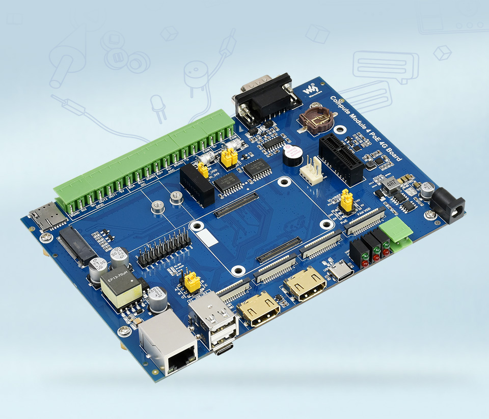
TheCompute Module 4 PoE 4G Board is an industrial grade IoT base board designed for Raspberry Pi Compute Module 4 (not included). It features communication functions including global 5G/4G/3G/2G cellular network, and PoE Ethernet. There are also various industrial isolated interfaces such as CAN, RS485, RS232, ADC, and GPIO, which make it an ideal choice for sorts of industrial IoT applications. Compared with the CM3 version, this one will provide more powerful processing performance.
- Compatible with Raspberry Pi Compute module 4 all variants
- M.2 slot for connecting separate communication module, global 5G/4G/3G/2G cellular network support
- 10/100M/1000M auto-negotiation Ethernet port, with PoE enabled
- USB HUB, allows connecting more USB devices
- USB TO UART, for serial debugging
- Provides various industrial isolated interfaces: CAN, RS485, RS232, ADC, GPIO, RTC
- Multiple video-related ports like HDMI, DSI, CSI
- LED indicators for monitoring operating status
| CM4 socket | suitable for all variants of Compute Module 4 |
|---|---|
| Networking | Gigabit Ethernet RJ45 connector, integrates 802.3af-compliant PoE circuit (5V/2.5A) |
| M.2 B KEY, supports 5G / 4G module | |
| SIM card slot, supports nano SIM card for 4G/3G/2G communication | |
| Connector | Isolated RS485, Isolated RS232, PCIe Gen 2 x1, I2C, ADC, GPIO |
| USB | Dual USB 2.0 Type A |
| Display | Dual MIPI DSI display ports (15pin 1.0mm FPC connector) |
| Camera | Dual MIPI CSI-2 camera ports (15pin 1.0mm FPC connector) |
| Video | Dual HDMI ports, supports 4K 30fps output |
| RTC | Real-time clock with battery socket and ability to wake Compute Module 4 |
| Storage | MicroSD card socket for Compute Module 4 Lite (without eMMC) variants |
| Fan header | allows speed adjustment and measurement, 5V / 12V input |
| Power input | 7V~36V wide range |
| Dimensions | 160 × 114mm |
| CM4 Base Board | Interface count and specifications | |||||||||||
|---|---|---|---|---|---|---|---|---|---|---|---|---|
| PoE | Gigabit ETH | 40PIN GPIO | PCIe | USB① | DSI | HDMI | CSI | RTC | Fan Header | Power Input | Features | |
 NANO A NANO A |
√ | 2.0×1 | ×1 | 5V | CM4 sized | |||||||
 NANO B NANO B |
×1 | √ | 2.0×1 | ×1 | ×1 | ×1 | 5V | CM4 sized | ||||
 NANO C NANO C |
√ | 2.0×1 | ×1 | ×1 | ×1 | 5V | Onboard Camera | |||||
 mini Base A mini Base A |
×1 | √ | M.2 M | 2.0×4 | ×1 | ×2 | ×2 | 5V | 5V | mini size | ||
| mini Base B |
×1 | √ | M.2 M | 2.0×4 | ×1 | ×2 | ×2 | √ | 5V | 5V | mini size | |
 mini Base C mini Base C |
×1 | √ | M.2 M | 2.0×2 | ×1 | ×2 | √ | 5V | 5V | Dedicated 40PIN LCD Connector | ||
 Touch screen Touch screen |
×1 | M.2 M | 2.0×4 | ×1 | ×1 | 5V | IPS screen | |||||
 Mini Dual Gigabit Mini Dual Gigabit |
×2 | √ | 2.0×1 | 5V SH1.0 | 5V | dual ETH | ||||||
 Binocular camera Binocular camera |
×1 | √ | M.2 M | 2.0×4 | ×2 | 5V | dual 8MP cameras | |||||
 4CH RS485 4CH RS485 |
×1 | 2.0×2 | ×1 | ×2 | ×1 | 5V | 7-36V | dual ETH | ||||
 WIFI6 DUAL ETH WIFI6 DUAL ETH |
×1 | √ | M.2 E | 2.0×3 | ×1 | ×2 | ×2 | ×1 | 5/12V | 7-36V | WIFI6 dual ETH | |
 Dual Gigabit ETH Dual Gigabit ETH |
×2 | √ | 3.0×3 | ×1 | ×2 | ×2 | √ | 5/12V | 7-36V | |||
 IoT Dual Gigabit ETH IoT Dual Gigabit ETH |
×2 | √ | 3.0×2 | ×1 | ×2 | ×2 | √ | 5/12V | 5V | 5G/4G support | ||
 IoT Base IoT Base |
√ | ×1 | Gen2×1 | 2.0×2 | ×2 | ×2 | ×2 | √ | 5/12V | 7-36V | 5G/4G supportRS232RS485ADC | |
 PoE Base (B) PoE Base (B) |
√ | ×1 | √ | Gen2×1 | 2.0×4 | ×2 | ×2 | ×2 | √ | 5/12V | 5V | RS232RS485 |
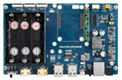 PoE UPS Base PoE UPS Base |
√ | ×1 | √ | M.2 M | 2.0×4 | ×1 | ×2 | ×2 | √ | 5/12V | 7-36V | UPS |
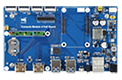 PoE Base PoE Base |
√ | ×1 | √ | 3.0×4 | ×2 | ×2 | ×2 | √ | 5/12V | 7-36V | ||
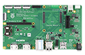 Raspberry Pi official Raspberry Pi official |
② | ×1 | √ | Gen2×1 | 2.0×4 | ×2 | ×2 | ×2 | √ | 12V | 12V | |
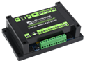 Wireless base Wireless base |
×1 | M.2 B / Mini-PCIe | 2.0×3 | ×1 | ×1 | √ | 5/12V | 5V or 7-36V | 5G/4G support RS485 CAN rail-mount | |||
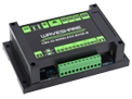 UPS Wireless base UPS Wireless base |
×1 | M.2 B | 2.0×3 | ×1 | ×1 | √ | 5/12V | 5V or 7-36V | With UPS 5G/4G support RS485 CAN rail-mount | |||
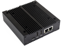 NAS Mini Computer NAS Mini Computer |
×2 | √ | M.2 M×2/ Mini-PCIe | 3.0×2 | ×2 | ×2 | √ | 5V | dual M.2 M KEY slots | |||
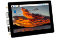 5″ touch screen 5″ touch screen |
② | ×1 | √ | M.2 M | 2.0×4 | ×1 | ×2 | √ | 5/12V | 5V | ||
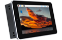 7″ all-in-one 7″ all-in-one |
×1 | M.2 M | 2.0×4 | used | ×1 | used | √ | 5/12V used | 7-36V | touch screen camera speaker | ||
 13.3″ all-in-one 13.3″ all-in-one |
×1 | 2.0×2 | 12V | HD touch screen | ||||||||
 13.3″ Magic Mirror 13.3″ Magic Mirror |
×1 | 2.0×2 | 12V | HD screen, Speech Assistant | ||||||||
| Note | ① USB 3.0 is equivalent to USB 3.2 Gen1 ② There's PoE header only on the Raspberry Pi official IO board without PoE circuit, that means additional PoE module is required for the official IO board to enable PoE feature. Unless otherwise specified, the PoE feature here stands for integrating 802.3af-compliant PoE circuit (5V/2.5A). | |||||||||||
Standard CM4 Socket, Suitable For All Variants Of Compute Module 4
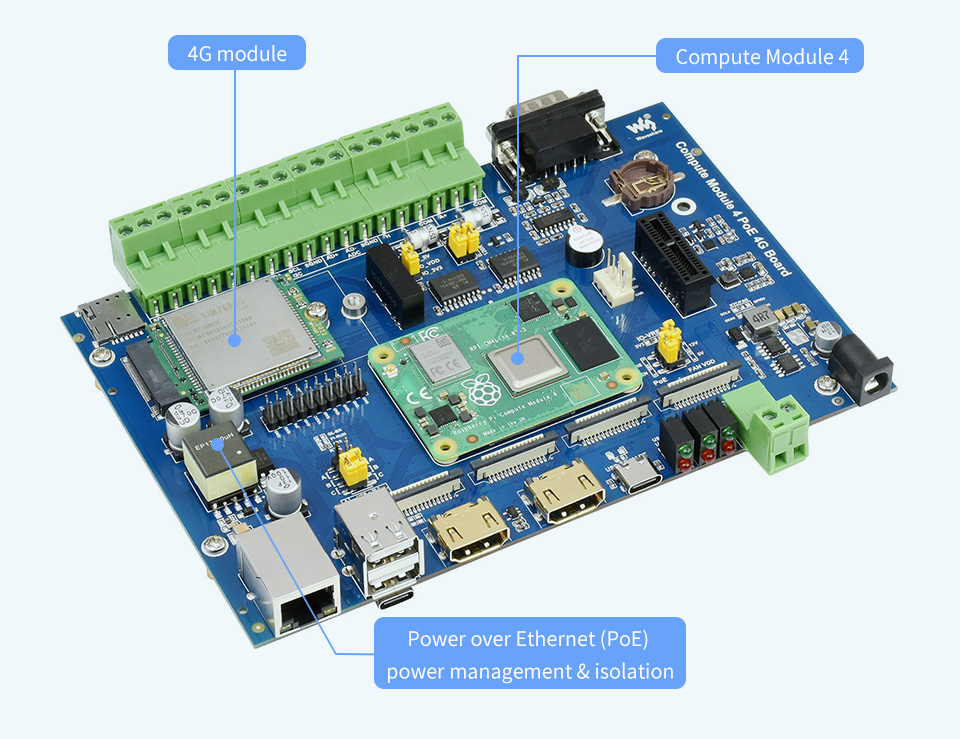
various interfaces including: M.2/CSI/DSI/HDMI/USB/ETH/PCIe/RS232/RS485
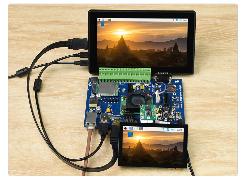
suitable for Raspberry Pi applications where multiple peripherals are requiredor other industrial context
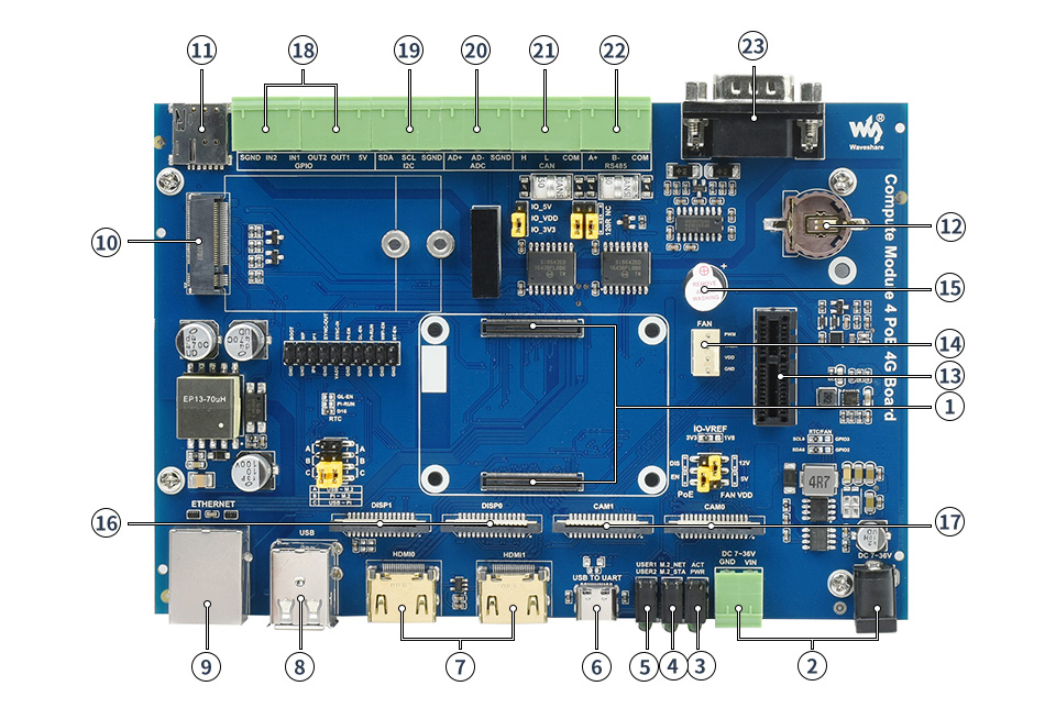
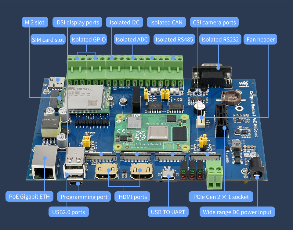
- Compute Module 4 socket for connecting Raspberry Pi Compute Module 4
- Power input 7-36V wide range power supply
- CM4 status indicator red: Raspberry Pi power indicator green: Raspberry Pi operating status indicator
- M.2 status indicator red: enabled indicator green: operating status indicator
- User LED handy for I/O output testing, or program running status monitoring
- USB TO UART for serial debugging
- HDMI dual HDMI ports, supports dual 4K 30fps output
- USB 2.0 dual USB 2.0 ports, for connecting USB devices
- RJ45 Gigabit Ethernet 10/100/1000M auto-negotiation Gigabit Ethernet port, with PoE Power Over Ethernet features
- M.2 slot for connecting 5G/4G communication module
- SIM card slot supports nano SIM card for 4G/3G/2G communication
- RTC real time clock battery holder supports CR1220 button cell
- PCIe Gen 2 × 1 socket
- Fan header for connecting cooling fan, allows speed adjustment and measurement
- Buzzer
- DISP dual MIPI DSI display ports
- CAM dual MIPI CSI camera ports
- Isolated GPIO allows controlling / detecting devices via GPIO
- Isolated I2C allows controlling / reading devices via I2C
- Isolated ADC ADC differential input
- Isolated CAN interface
- Isolated RS485 interface
- Isolated RS232 interface
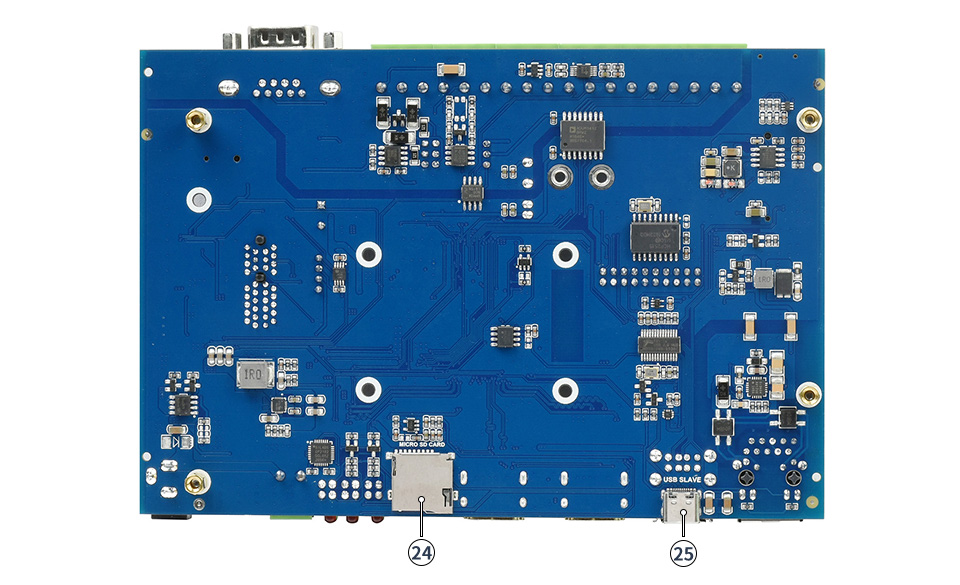
- Micro SD card slot (bottom side) insert a Micro SD card with pre-burnt system, to start up Compute Module 4 Lite
- USB-C programming port (bottom side) allows burning system image into Compute Module 4 eMMC variants
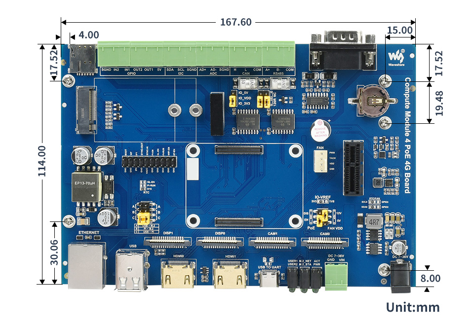


* Resources for different product may vary, please check the wiki page to confirm the actually provided resources.
Lieferumfang
- Compute Module 4 PoE 4G Board x1
Payment methods
Payment methods


